The fastest diagnosis is not a voltage test or an adjustment. It is deciding how much of the system failed. A controller and seven-way problem can affect every wheel. A broken wire, weak magnet, grease-soaked lining or damaged spring usually shows up at one wheel first. Keep those two paths separate.
Use this symptom map first
| What the driver notices | First system to prove |
|---|---|
| Controller says no trailer or disconnected | Complete brake-output circuit through the connector, magnets and ground |
| All wheels feel weak | Controller mode/gain, common voltage delivery, common ground and adjustment history |
| One wheel contributes little or nothing | That wheel's branch wire, magnet, adjuster and friction parts |
| All wheels grab or lock | Controller gain/boost, brake type selection and unintended brake-output voltage |
| One wheel grabs or runs hot | Local adjustment, hardware, drum, bearing and contamination |
| Brakes stay applied after a cable event | Breakaway pin, switch, cable routing and brake circuit |
Record the installed system before touching it
Write down the brake-controller brand and model, axle manufacturer and serial information, brake size, number of braking wheels and whether the trailer uses electric drum or electric-over-hydraulic brakes. Confirm whether the drum brakes are manual-adjust or forward self-adjusting. The controller mode and test expectations have to match the hardware.
Take a photo of the controller message and the axle label. Intermittent evidence is easy to lose after unplugging the seven-way or cycling the ignition.
Step 1: read the controller as a circuit monitor
A modern controller does more than send power. Many models look for a complete electrical path through the brake-output wire, brake magnets and return ground. For example, Tekonsha lists an open blue brake-output circuit or an open brake ground as primary causes when a Prodigy P3 reports no trailer connected.
- Record the exact wording: no trailer, open ground, overload, output short, power loss and internal error are not interchangeable.
- Confirm the controller is set for electric brakes rather than electric-over-hydraulic, if the model offers both.
- Notice whether the manual lever produces output while the brake pedal does not. A proportional controller may produce little automatic output while stationary, and the stop-lamp input still matters.
- Do not replace the controller until its power, ground, stop input and output circuit have been tested by its manual.
Step 2: inspect the seven-way connection
Disconnect with the vehicle and trailer secured. Look at both halves of the connector for water, green or white corrosion, overheated plastic, spread contacts, pushed-back terminals and a cable that becomes tight during turns. A connector can carry lights yet fail the higher-current brake path or its ground under load.
If the warning only appears over bumps or in turns, a helper can watch the controller while the stationary connector and accessible harness are moved gently. Do not perform a wiring experiment in traffic.
Step 3: decide whether every wheel or one wheel failed
With the trailer secured and following the axle maker's test method, compare every brake. A soft click or hum during manual override can identify a wheel that is receiving some magnet current. It cannot prove that the current is correct or that the shoes apply against the drum.
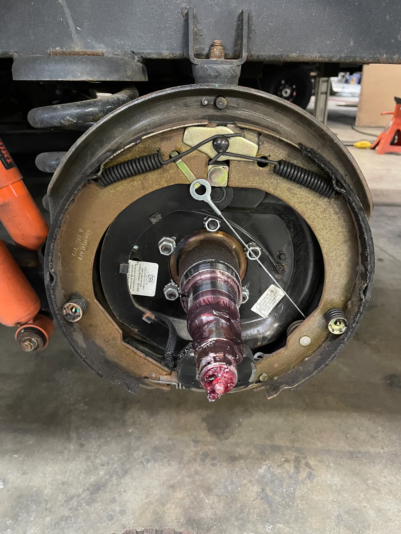
- Every brake silent or weak: stay upstream at controller settings, the seven-way, common brake wire and common ground.
- One wheel different: inspect the branch connection and that wheel's magnet and mechanical assembly.
- One wheel hot: inspect the brake and bearing together. Heat cannot identify which one failed by itself.
Step 4: test voltage and current without being fooled
Expected current depends on brake size and number of magnets. Follow the axle manual rather than copying a number from another trailer. Dexter's brake FAQ says its seven-inch brake uses about 2.5 amps per magnet and its other common electric magnets about 3 amps per magnet, but that is Dexter-specific guidance and the exact installed brake still controls.
A no-load voltage reading can look normal through a poor connection. Useful measurements are made while the brakes are commanded, with a meter and method rated for the circuit. Compare total draw with the expected number of magnets, then compare individual branches. Advanced current testing, live probing and under-trailer work belong with a trailer technician when the setup cannot be made safe.
Step 5: inspect adjustment and the drum assembly
Manual-adjust brakes lose effectiveness as lining-to-drum clearance grows. Dexter recommends adjustment after the first 200 miles, then at 3,000-mile intervals or as use and performance require for its manual-adjust products. Forward self-adjusting brakes still need correct installation, initial setup and inspection.
Inside the drum, look for worn or cracked lining beyond service limits, grease or oil contamination, a grooved magnet face, broken or stretched springs, a seized actuating lever, a damaged adjuster and an out-of-round or heavily scored drum. Brake dust should be handled by the service manual; do not blow unknown lining dust into the air.
Weak, locking and dragging brakes need different corrections
All brakes are weak
Check controller mode, gain and boost; common voltage drop and ground; adjustment; loaded trailer weight; and whether new shoes or drums completed the specified burnish process. Dexter notes that not every loaded combination will lock its wheels. Smooth controlled stopping—not tire skidding—is the target.
All brakes grab or lock
Verify controller setup first. Too much gain or aggressive boost can affect the whole trailer. If brakes apply without a command, stop and investigate a short-to-power, contaminated connector, incorrect wiring or breakaway activation.
One brake grabs, drags or stays hot
Do not hide one-wheel trouble by reducing controller gain until every other brake becomes weak. Inspect that wheel for over-adjustment, broken hardware, a seized lever, an out-of-round drum, seal leakage and bearing damage.
Test the breakaway system as a separate safety circuit
The breakaway battery and switch should apply the trailer brakes if the trailer separates from the tow vehicle. A battery indicator only reports what that kit was designed to measure; it does not automatically prove the switch, wiring and every wheel brake operate.
Use the exact kit instructions. Some procedures require disconnecting the seven-way and safely raising wheels. CURT's current 52042 instructions, for example, specify a wheel-rotation test and a timed hold test, followed by battery recharging. Another kit may use a different procedure. Never use the breakaway switch as a parking brake.
Before returning to the road
- The controller recognizes the trailer consistently through turns and a stationary harness movement check.
- Every required wheel brake responds and releases.
- No drum or hub becomes a clear temperature outlier during a cautious test.
- Controller gain is set with the trailer loaded, using the controller instructions.
- New friction parts have completed the required burnish procedure.
- Breakaway battery, switch, cable and brake application pass the kit's test.
FAQ
Why do the trailer brakes work with the manual lever but not the pedal?
Check the controller's stop-lamp input and setup. Proportional controllers can also produce little automatic output while the vehicle is stationary. Use the controller's own diagnostic menu and instructions before blaming the trailer.
Does a humming magnet prove the brake works?
No. It is a helpful comparison clue, but adjustment, shoe condition, contamination, drum condition and actual current still matter.
Should every electric trailer brake lock during setup?
No universal lockup test applies to every trailer. Load, brake design, tire size and road surface change the result. Follow the controller and axle procedures and aim for stable, effective braking.
Related brake and hub help
- Brake controller says no trailer connected
- Trailer brakes weak even at high gain
- Trailer brakes locking or grabbing
- One trailer wheel or hub is hot
- Breakaway switch and battery test
- Wheel bearing and hub inspection guide
Sources and review notes
Reviewed July 18, 2026. Brake size, current draw, adjustment direction, wear limits, torque, bearing adjustment and test procedures must come from the manuals for the installed axle, controller and breakaway kit.
Match the symptom before picking up tools
The towing troubleshooter now separates weak, missing, locking, dragging, breakaway and hot-hub symptoms.
Start towing diagnosisFind trailer service